 Dispersion relation
 Dispersion relation
 When using the more complicated plasma theories,
the resulting dispersion relations can be diffucult to interpretate. Because of
this, different kind of graphical presentations can been used.
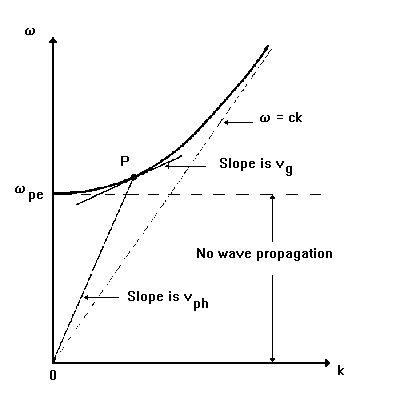
The most obvious one is to plot w=w(k) in a (k,w) plane:
Dispersion relation w(k) for the transverse wave propagating in an isotropic cold electron plasma. Note the geometrical representation of the phase and group velocities at the point P.
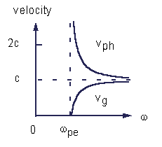
Other possibility is to plot the phase (and possibly group) velocities as a
function of w:

Same dispersion relation as above, but now as v=v(w) for both phase and group velocities. Note the reflection point at w(pe).
Wave propagation can also be described using diagrams called phase velocity or wave normal surfaces, which give the variations of the magnitude of the phase velocity of plane waves with respect to the magnetic field direction:
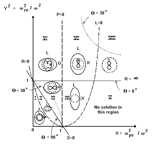
Finally, the CMA (Clemmow-Mullaly-Allis) diagram is a very compact alternative way for presenting solutions of the dispersion relation. This diagram is constructed in a two-dimensional parameter space having X=(w(pe)/w)^2 as the horizontal axis, and Y^2=(w(ce)/w)^2 as the vertical axis, and displaying all the resonances and reflection points as a function of both X and Y^2. Thus, in this diagram, the magnetic field increases in the vertical direction, the plasma electron density increases in the horizontal direction, and the electromagnetic wave frequency decreases in the radial direction (in each case, considering all other parameters fixed). Furthermore, the CMA diagram divides the (X,Y^2) plane into a number of regions such that within each region the characteristic topological forms of the phase velocity surfaces remain unchanged.
 The CMA diagram for waves in a cold electron gas. The solid lines represent
the principal resonances and the dashed lines the reflection points.
The CMA diagram for waves in a cold electron gas. The solid lines represent
the principal resonances and the dashed lines the reflection points.See also: